As devices like drones, robots, and power banks evolve towards higher power and longer endurance, the charging efficiency of their core cells has become a key factor affecting operational continuity. Recently, TP launched the INR21700-50SG cell. Positioned as a high-capacity, high-rate cylindrical cell, with a nominal 5.0Ah capacity and 35A continuous discharge current, it meets the demands of high-power output.
In this review, we test this cell's charge and discharge performance at various rates. The tests are conducted at room temperature, 25±2°C. According to the official website, this cell supports up to 6A continuous charging and 20A continuous discharge (without triggering temperature cutoff). Let's see the actual test results.
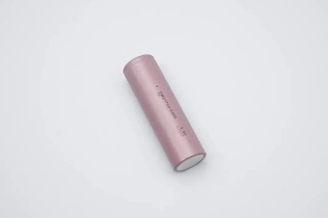
The cell features a brown sleeve, smooth and tidy surface without damage, printed with basic information.
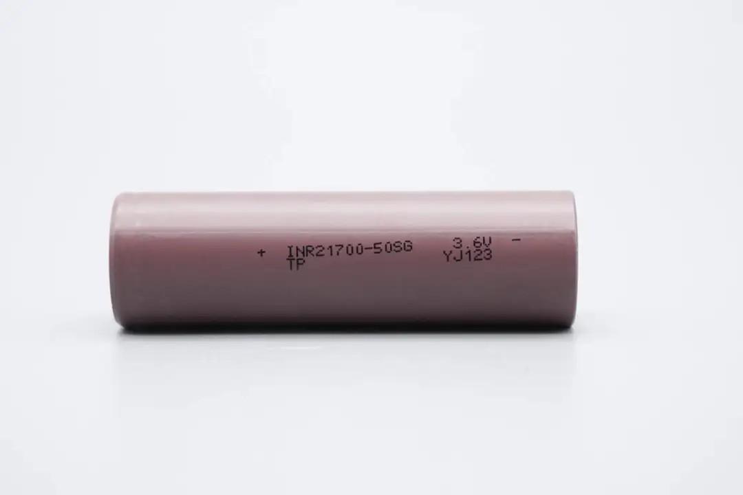
Brand: TP; Model: INR21700-50SG; Nominal Voltage: 3.6V; Factory Code: YJ123.
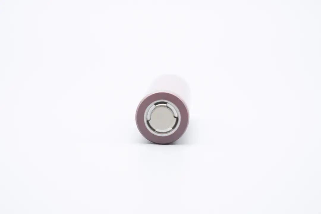
The cell's positive terminal cap is made of alloy, with a flat-top design, featuring three vent holes visible on the top.
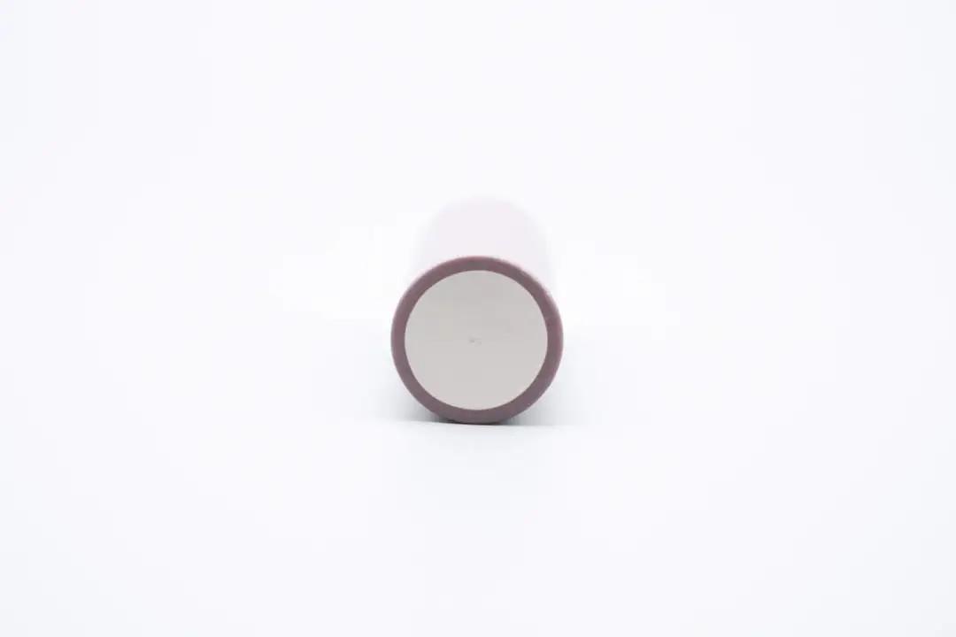
The cell's negative terminal is made from alloy metal treated with an anodic oxidation process, making it durable and corrosion-resistant. The surface is clean, without stains or signs of oxidation.
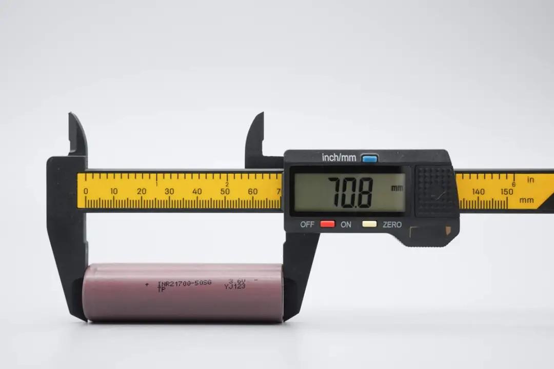
Measured with plastic calipers, the cell height is approximately 70.8mm.
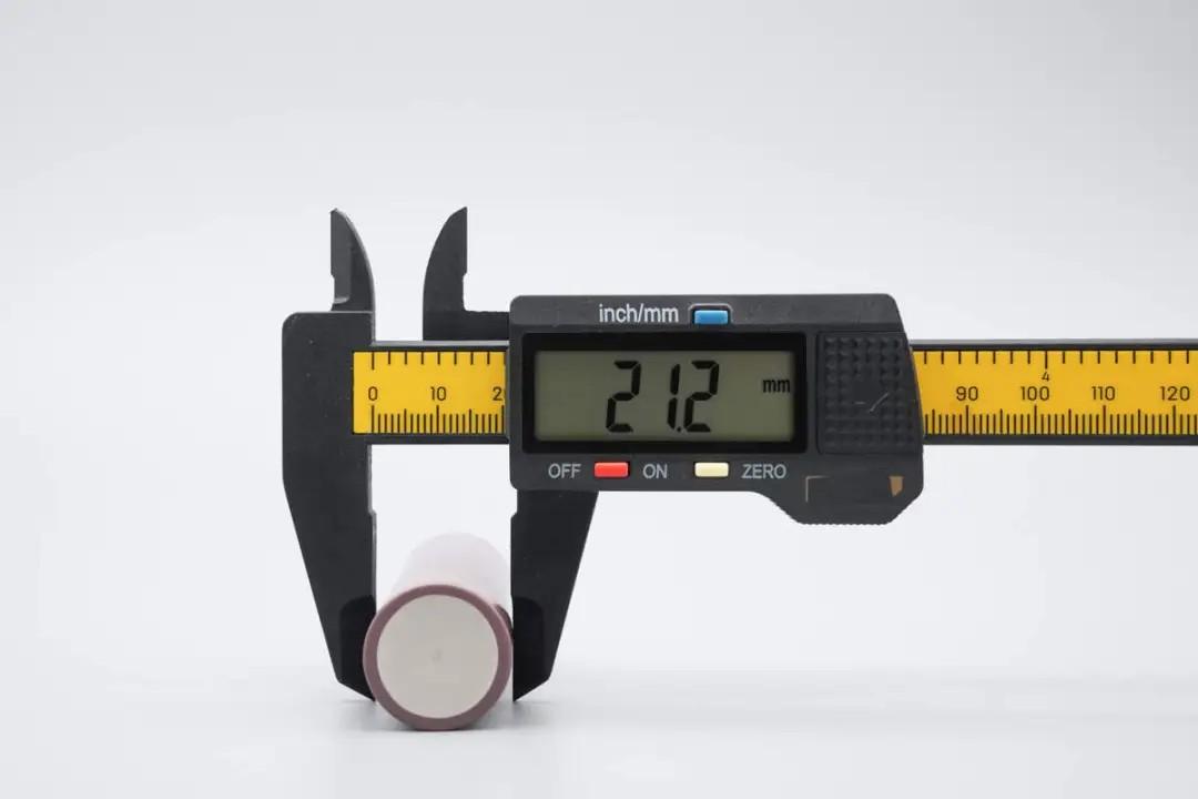
Measured with plastic calipers, the cell diameter is approximately 21.2mm.
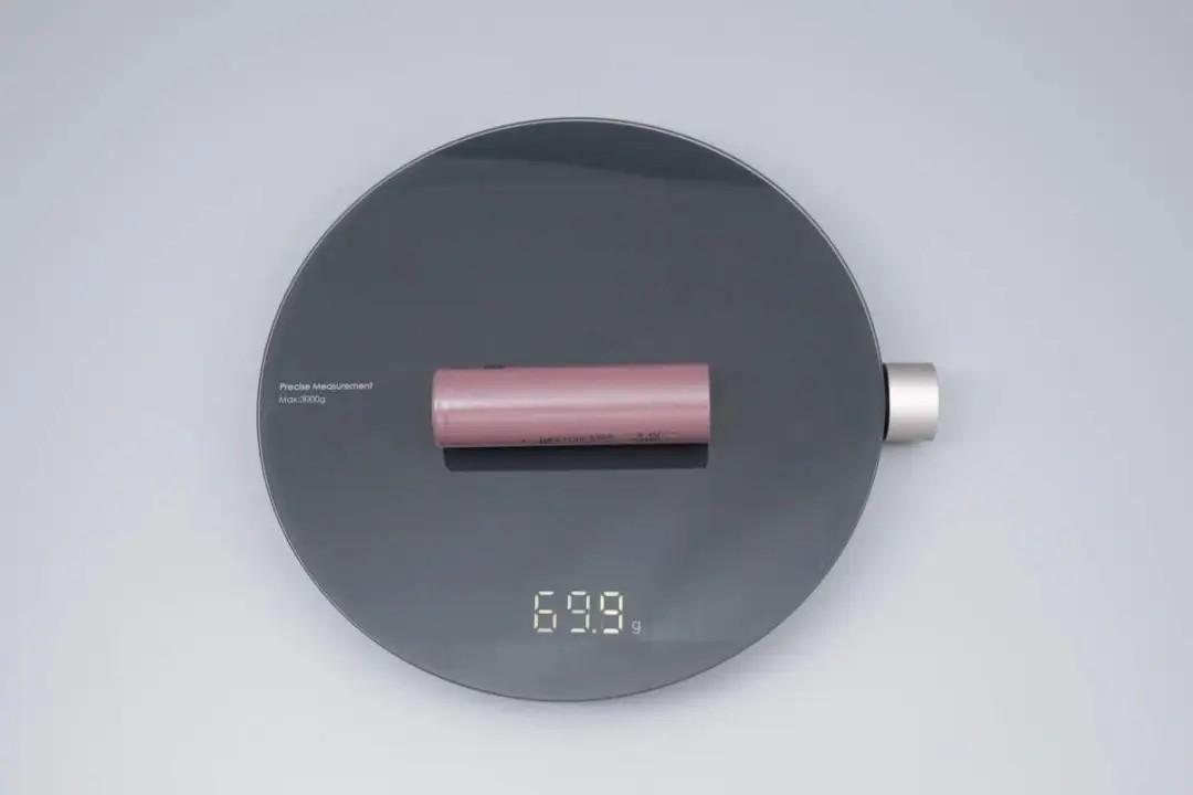
Weight is approximately 69.9g.
Now, let's proceed to the main topic: multi-rate charging tests. The charging test involves Constant Current Constant Voltage (CCCV) charging, recording the total duration.
0.2C Charging
First, charging the TP INR21700-50SG cell at 0.2C, set current to 1000mA, charge cutoff voltage to 4.2V.
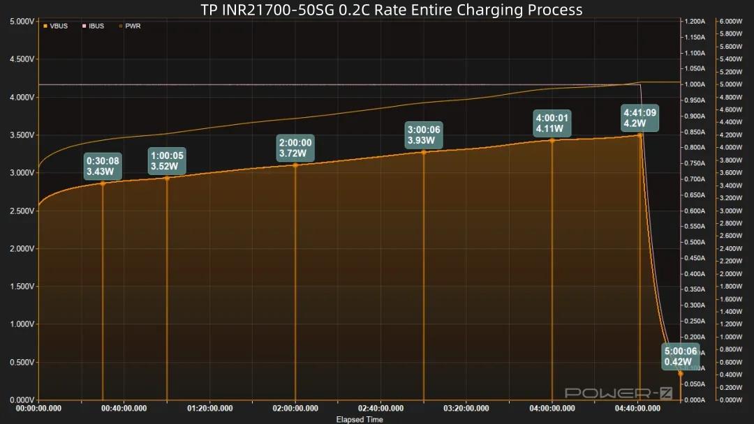
After power-on, voltage and power rise continuously. Power peaks at around 4.2W at 4 hours and 41 minutes, then power decreases and trickle charging begins. Charging completes 19 minutes later, total time 5 hours.
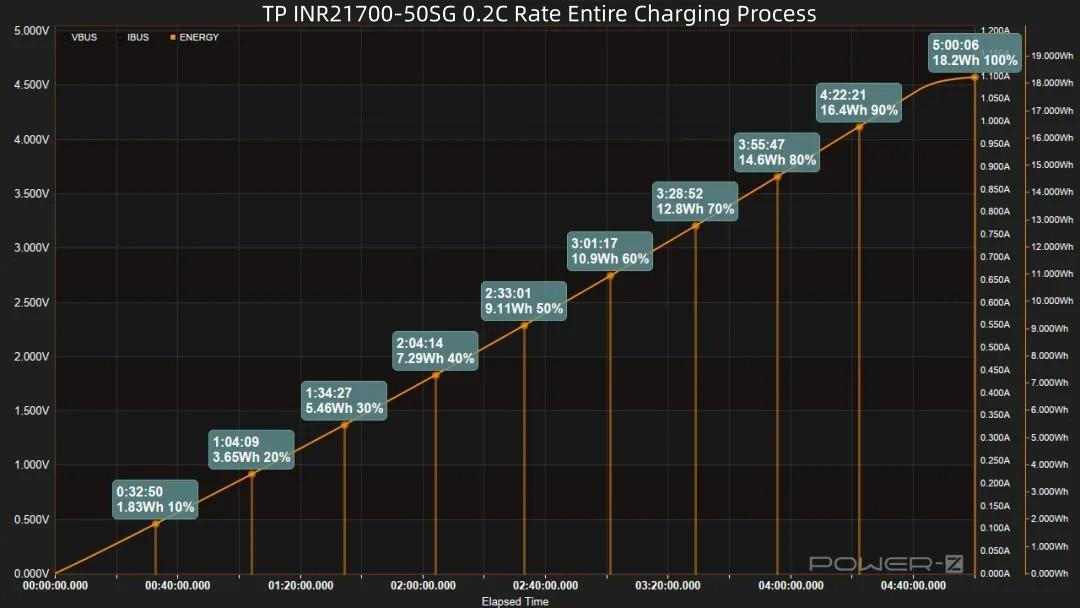
Regarding the capacity curve: Reaching 20% takes 1 hour 4 minutes, reaching 30% takes 1 hour 34 minutes. After 60 minutes, 50% capacity is charged, with 9.11Wh energy input. At 3 hours 55 minutes, 80% capacity is charged, with 14.6Wh energy input. A full charge takes 5 hours, with a total energy input of 18.2Wh.
0.5C Charging
Charging the TP INR21700-50SG cell at 0.5C, set current to 2500mA, charge cutoff voltage to 4.2V.
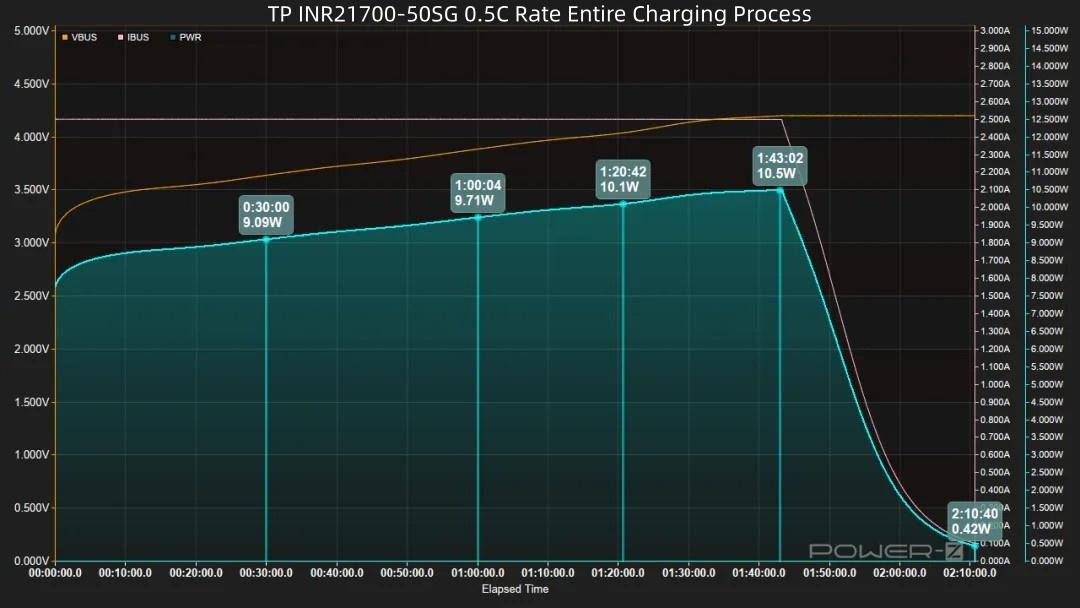
After power-on, voltage and power rise continuously. Power peaks at around 10.5W at 1 hour 43 minutes, while voltage reaches 4.2V. Then power decreases and trickle charging begins. Charging completes 27 minutes later, total time 2 hours 10 minutes.
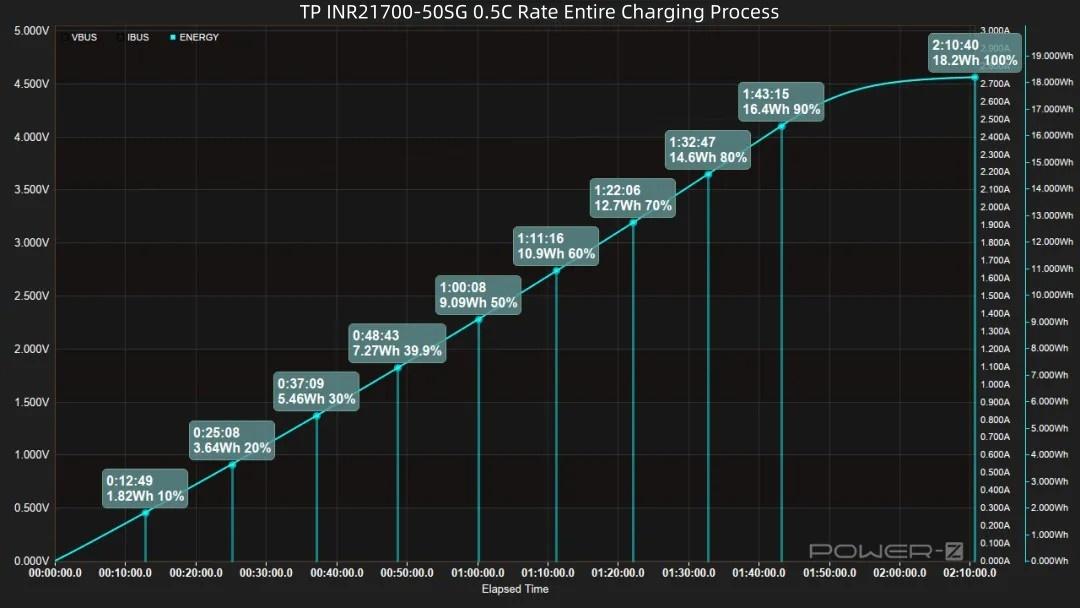
Looking at the capacity curve: Reaching 20% takes 25 minutes, reaching 30% takes 37 minutes, reaching 50% takes 1 hour (9.09Wh energy input). 32 minutes later, 80% capacity is charged (14.6Wh energy input). 10 minutes later, 90% capacity is charged. A full 100% charge takes 2 hours 10 minutes, with a total energy input of 18.2Wh.
1C Charging
Charging the TP INR21700-50SG cell at 1C, set current to 5000mA, charge cutoff voltage to 4.2V.
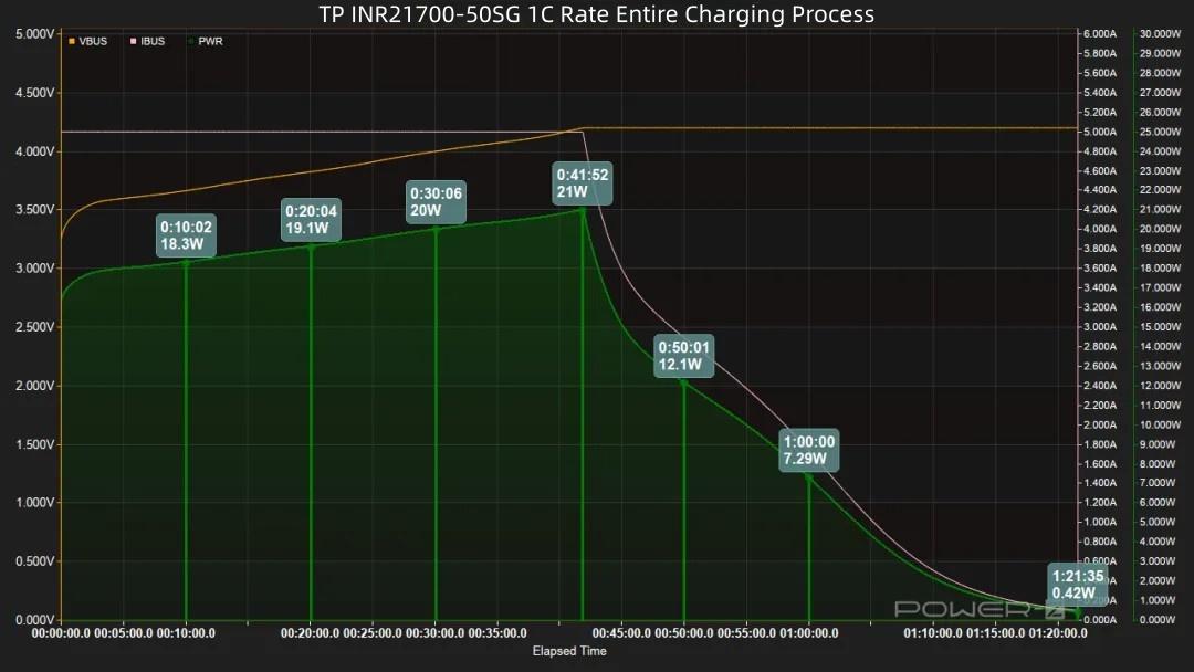
After power-on, voltage and power rise continuously. Voltage reaches 4.2V at around 41 minutes, power peaks at 21W, then trickle charging begins. Charging completes 40 minutes later, total time 1 hour 21 minutes.
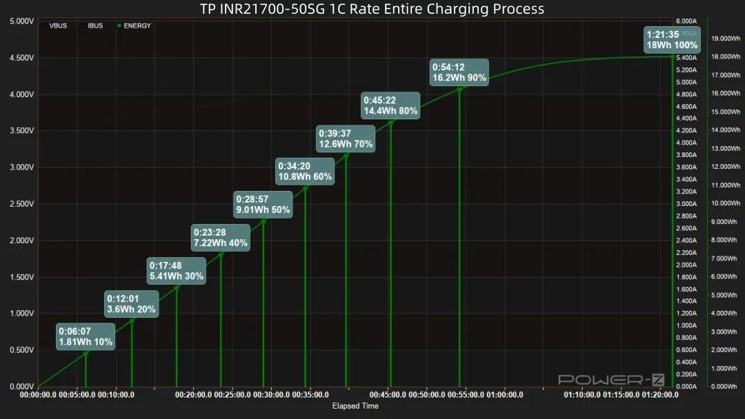
Regarding the capacity curve: Reaching 20% takes 12 minutes, reaching 30% takes 17 minutes, reaching 50% takes 28 minutes (9.01Wh energy input). 17 minutes later, 80% capacity is charged (14.6Wh energy input). 9 minutes later, 90% capacity is charged. A full 100% charge takes 1 hour 21 minutes, with a total energy input of 18Wh.
1.2C Charging
Charging the TP INR21700-50SG cell at 1.2C, set current to 6000mA, charge cutoff voltage to 4.2V.
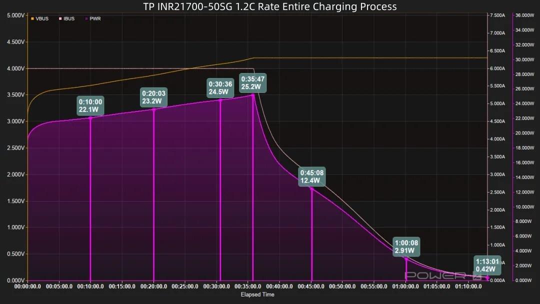
After power-on, voltage and power rise continuously. Voltage reaches 4.2V at around 41 minutes, power peaks at 21W, then power decreases and trickle charging begins. Charging completes 38 minutes later, total time 1 hour 13 minutes.
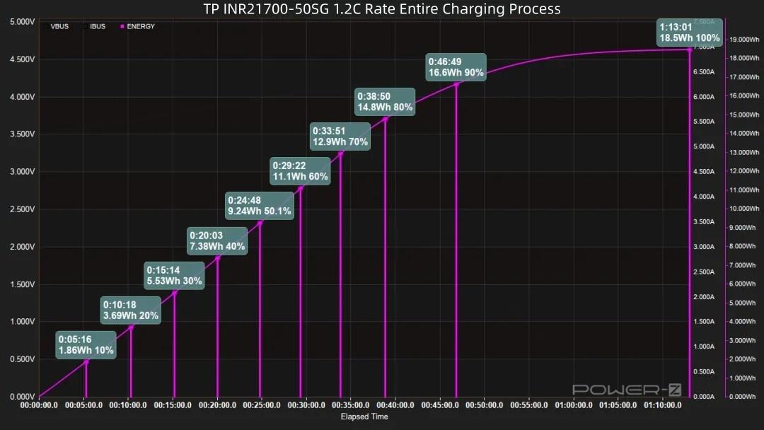
Combined with the graph: Reaching 20% takes 10 minutes, reaching 30% takes 15 minutes, reaching 50% takes 24 minutes (9.24Wh energy input). 14 minutes later, 80% capacity is charged (14.8Wh energy input). 8 minutes later, 90% capacity is charged. A full 100% charge takes 1 hour 13 minutes, with a total energy input of 18.5Wh.
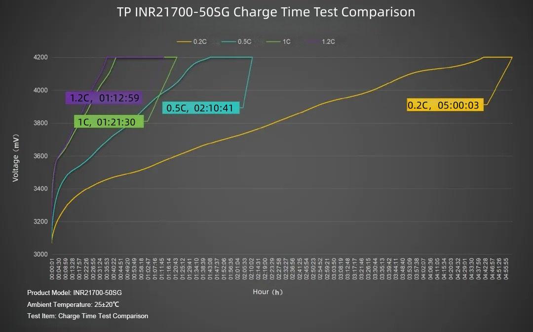
Summarizing the curves in a table: The slowest charge rate is 0.2C, taking 5 hours. The fastest is 1.2C, taking 1 hour 12 minutes, followed by 1C at 1 hour 21 minutes, and 0.5C at 2 hours 10 minutes.
The discharge test uses constant current discharge at 25±2°C, recording total duration, delivered capacity, and energy.
0.2C Discharge
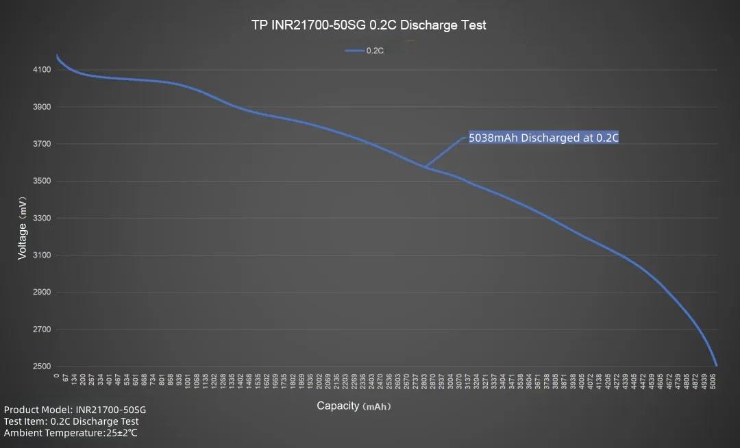
Plotting the line graph, set current to 1000mA, discharging the TP INR21700-50SG at 0.2C. Average voltage 3.58V, discharge cutoff voltage 2.5V. Duration about 5 hours 1 minute. Delivered capacity 5038mAh, delivered energy 18.06Wh.
0.5C Discharge
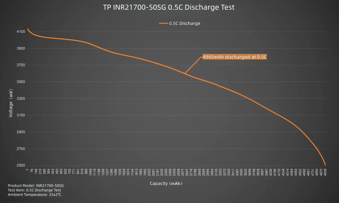
Plotting the line graph, set current to 2500mA, discharging the TP INR21700-50SG at 0.5C. Average voltage 3.56V, discharge cutoff voltage 2.5V. Duration about 1 hour 58 minutes. Delivered capacity 4945mAh, delivered energy 17.6Wh.
1C Discharge
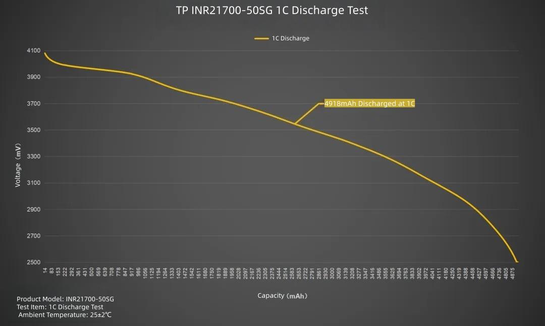
Plotting the line graph, set current to 5000mA, discharging the TP INR21700-50SG at 1C. Average voltage 3.52V, discharge cutoff voltage 2.5V. Duration about 59 minutes. Delivered capacity 4918mAh, delivered energy 17.29Wh.
2C Discharge
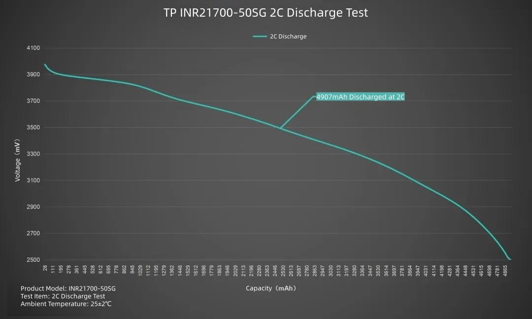
Plotting the line graph, set current to 10000mA, discharging the TP INR21700-50SG at 2C. Average voltage 3.44V, discharge cutoff voltage 2.5V. Duration about 29 minutes. Delivered capacity 4907mAh, delivered energy 16.88Wh.
3C Discharge
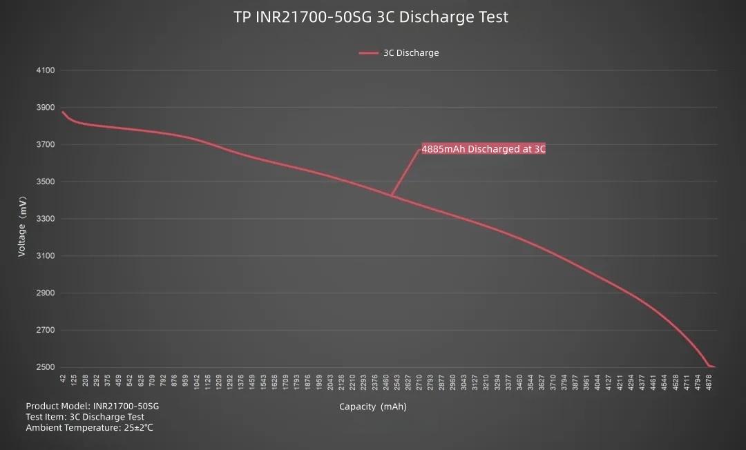
Plotting the line graph, set current to 15000mA, discharging the TP INR21700-50SG at 3C. Average voltage 3.38V, discharge cutoff voltage 2.5V. Duration about 19 minutes. Delivered capacity 4885mAh, delivered energy 16.49Wh.
4C Discharge
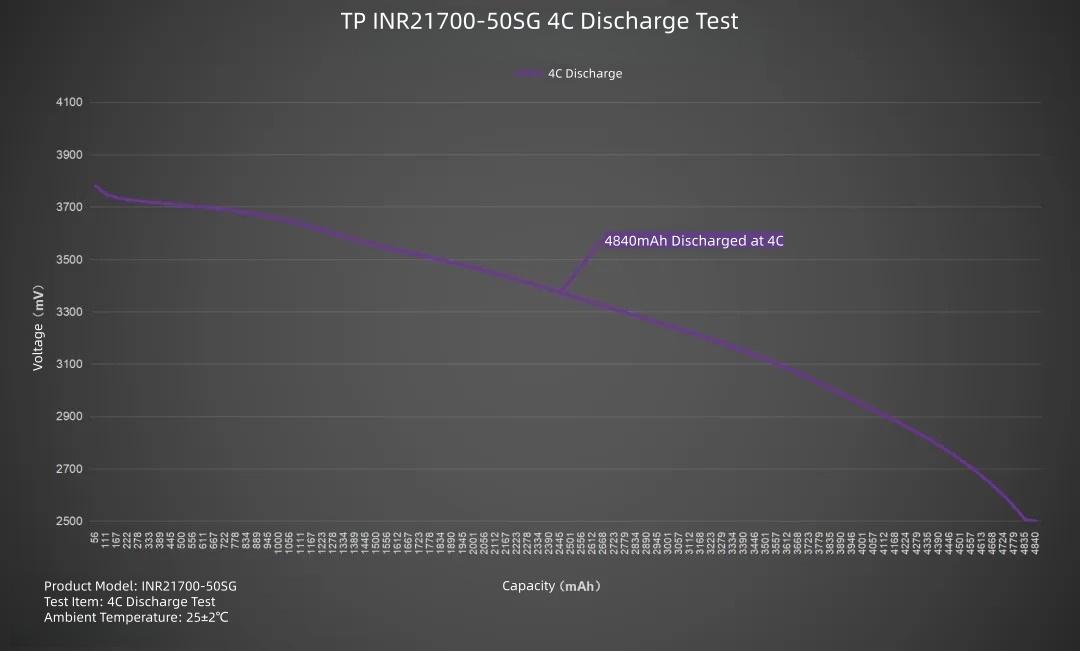
Plotting the line graph, set current to 20000mA, discharging the TP INR21700-50SG at 4C. Average voltage 3.32V, discharge cutoff voltage 2.5V. Duration about 14 minutes. Delivered capacity 4840mAh, delivered energy 16.06Wh.
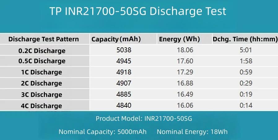
Summarizing the data in a table clearly shows the performance release at each rate. The test results indicate overall moderate performance.
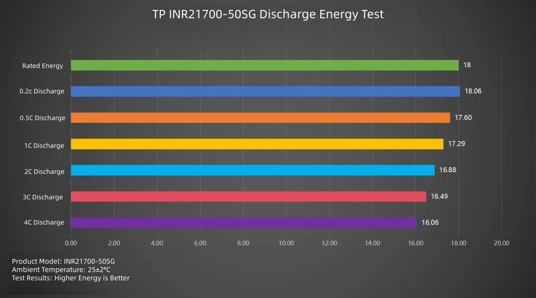
Looking in detail at the discharge energy performance: Discharge energy decreases as the rate increases. The highest energy delivery is at 0.2C (18.06Wh), followed by 0.5C (17.6Wh). The other levels gradually decrease, with the lowest at 4C (16.06Wh).
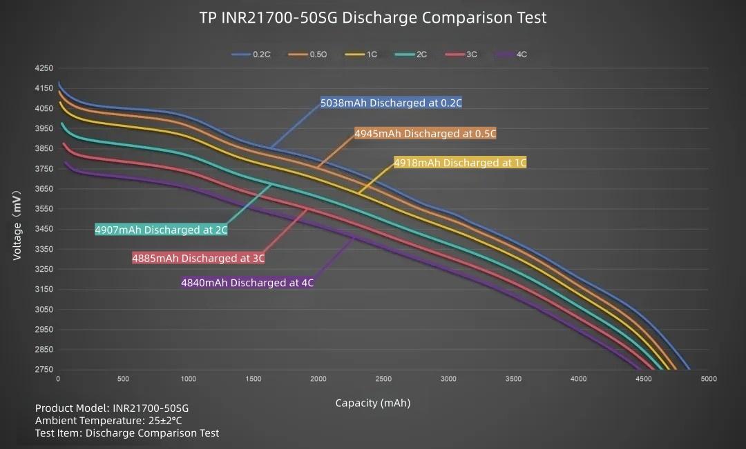
Summarizing the data in a curve graph: The highest delivered capacity is at 0.2C (5038mAh), followed by 0.5C (4945mAh). As the rate increases, the delivered capacity continuously decreases, reaching 4840mAh at 4C. Overall discharge performance is moderate.
For the internal resistance test, the battery exchange network uses an internal resistance tester to measure the fully charged internal resistance and the empty internal resistance.
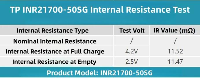
Summarizing the test data in a table: Fully charged internal resistance voltage is 4.2V, empty internal resistance voltage is 2.5V. The nominal internal resistance of the TP INR21700-50SG cell is unknown.
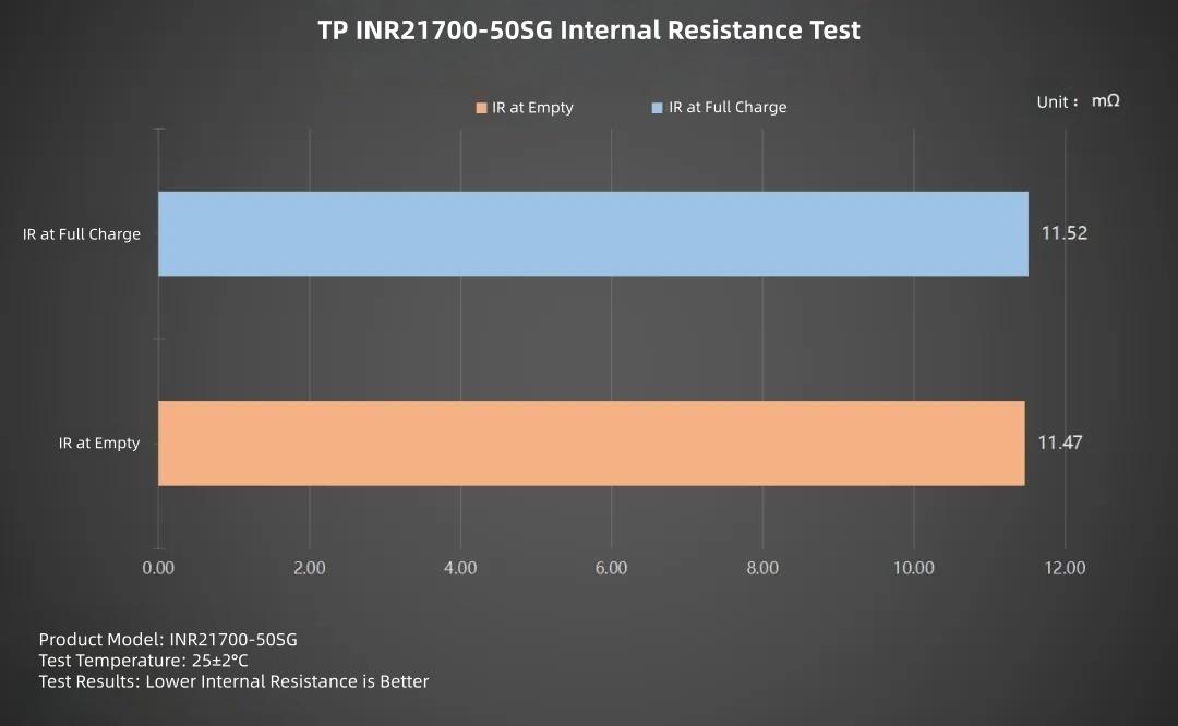
Plotting the bar chart: The 4.2V full charge internal resistance is 11.52mΩ, the 2.5V empty internal resistance is 11.47mΩ. The internal resistance difference between the two voltages is small.
For the temperature test, the battery exchange network will measure the surface temperature using an infrared thermal imager after 30 minutes of charging at each rate.
Charging Temperature Test
0.2C Charging
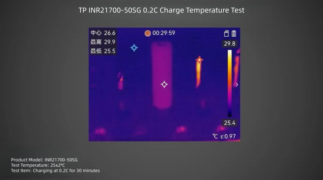
TP INR21700-50SG cell charged at 0.2C rate for 30 minutes, surface center temperature is about 26.6°C.
0.5C Charging
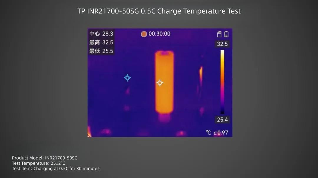
TP INR21700-50SG cell charged at 0.5C rate for 30 minutes, surface center temperature is about 28.3°C.
1C Charging
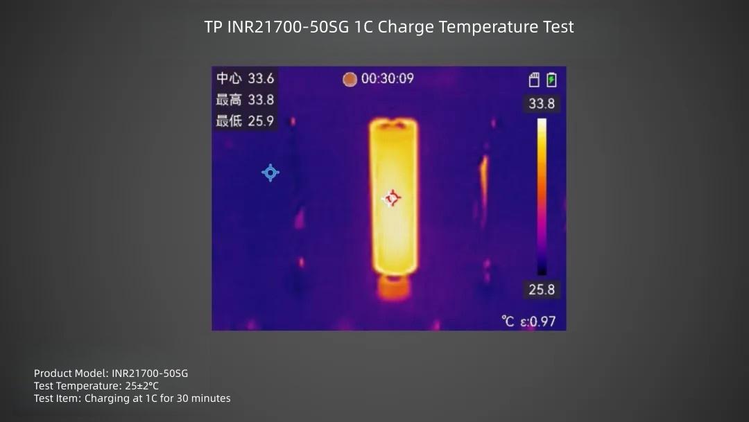
TP INR21700-50SG cell charged at 1C rate for 30 minutes, surface center temperature is about 33.8°C.
1.2C Charging
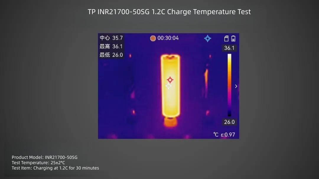
TP INR21700-50SG cell charged at 1.2C rate for 30 minutes, surface center temperature is about 36.1°C.
0.2C Discharge
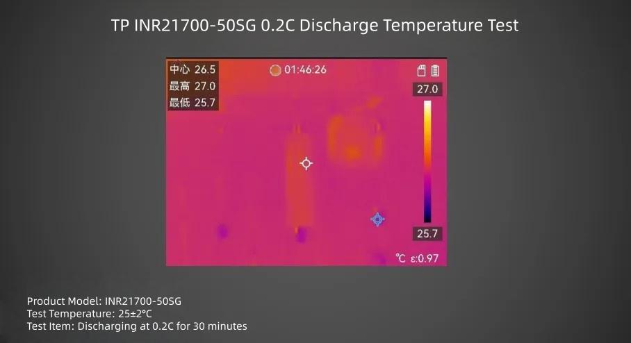
TP INR21700-50SG cell discharged at 0.2C rate for 30 minutes, surface center temperature is about 28.9°C.
0.5C Discharge
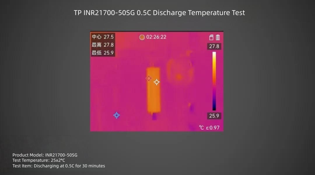
TP INR21700-50SG cell discharged at 0.5C rate for 30 minutes, surface maximum temperature is about 27.8°C.
1C Discharge
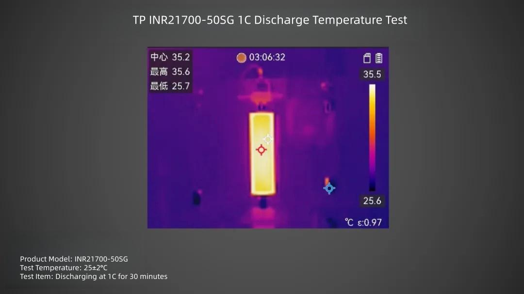
TP INR21700-50SG cell discharged at 1C rate for 30 minutes, surface maximum temperature is about 35.6°C.
2C Discharge
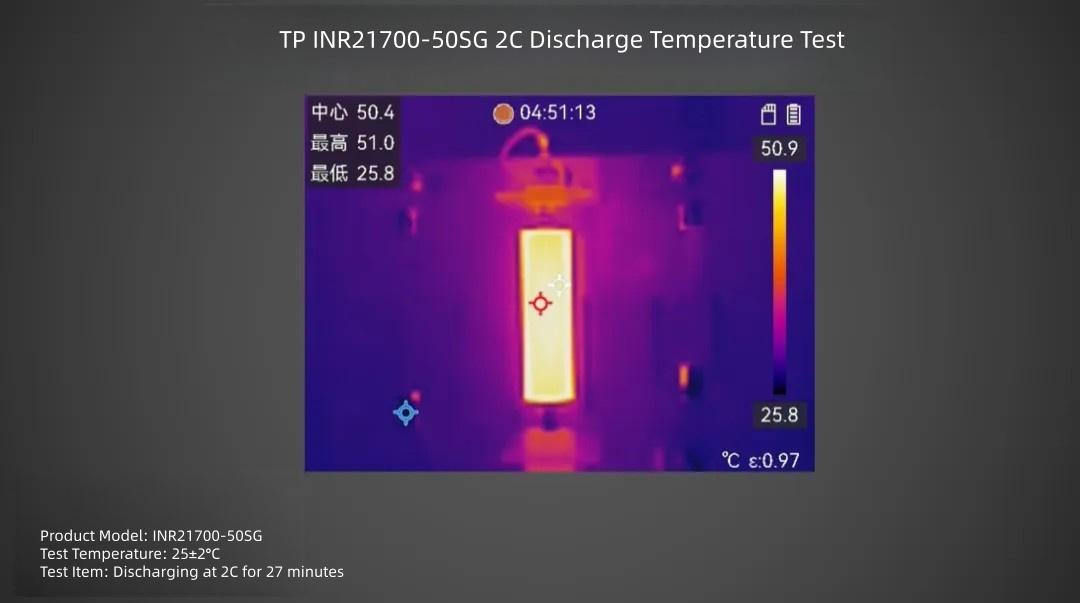
TP INR21700-50SG cell discharged at 2C rate for 27 minutes, surface maximum temperature is about 51°C.
3C Discharge
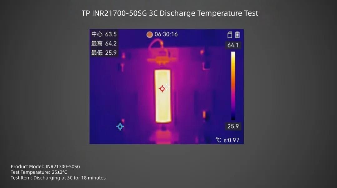
TP INR21700-50SG cell discharged at 3C rate for 18 minutes, surface maximum temperature is about 64.2°C.
4C Discharge
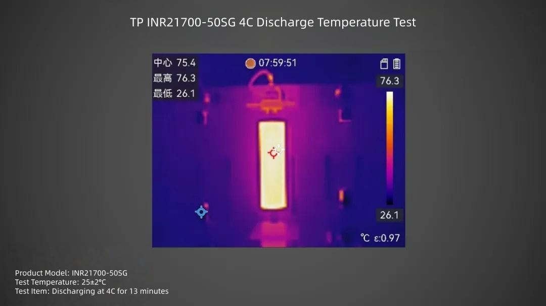
TP INR21700-50SG cell discharged at 4C rate for 13 minutes, surface maximum temperature is about 76.3°C.
The INR21700-50SG is a high-capacity, high-rate type cell recently released by TP, primarily targeting robots with diverse loads and high-intensity movement, drones requiring long endurance under heavy payloads, and high-power power banks. Leveraging technological breakthroughs in "high-rate discharge, large capacity storage, fast charging, and long cycle life," it provides a new energy solution for high-power demands across multiple fields.
Based on the tests above, the TP INR21700-50SG cell's charge and discharge performance demonstrates distinct scenario adaptability. High-power levels suit scenarios demanding strict recharging speed, conventional power levels balance lifespan and efficiency, and low-power levels better fit long-term cycling needs. These three performance tiers together form its core advantage in handling diverse scenarios. For high-power charging scenarios, matching heat dissipation design and fast-charging modules are key to unleashing the cell's full potential.
Next:None
Previous:Zero or Low Voltage in LiFePO4 Batteries: Common Causes and Troubleshooting Guide