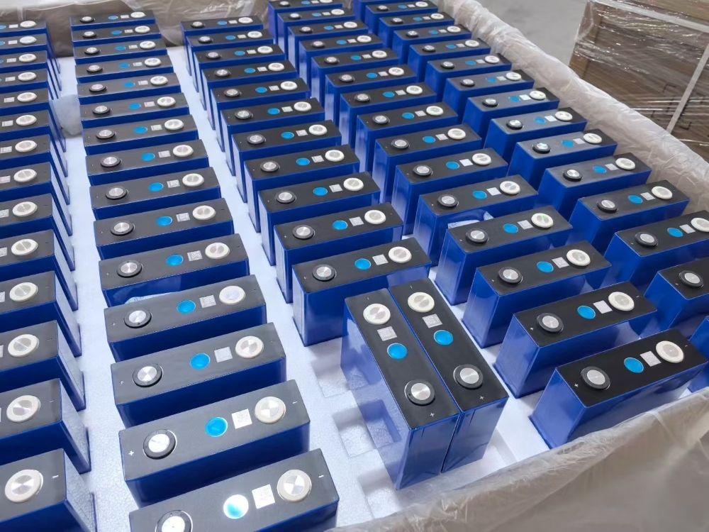
For LiFePO4 batteries, charging voltage is one of the most consequential settings in the entire system. If the voltage is too high, cells age faster. If it is too low, the pack may never reach full capacity. System integrators, installers, and procurement teams who specify energy storage projects therefore need more than a rough number: they need the correct charge voltage for each pack architecture. That setting influences cycle life, usable capacity, and whether the BMS will interrupt operation unnecessarily. This guide reviews per-cell voltage, common 12V, 24V, and 48V configurations, the CC-CV charging method, temperature constraints, BMS protection, and field recommendations for commercial and industrial systems.
A single lithium iron phosphate cell is nominally 3.2V. Its standard maximum charge voltage is 3.65V. That 3.65V value represents the upper boundary at which the cell approaches a full state of charge. It is a limit to respect, not a level that must be reached on every charging cycle.
Cells connected in series produce a pack voltage equal to the sum of the individual cell voltages. A 4S pack therefore reaches 14.6V when fully charged, an 8S pack reaches 29.2V, and a 16S pack reaches 58.4V. These figures appear on many charger datasheets, but the final setting should always be checked against the cell manufacturer’s specification and the BMS configuration.
| Pack layout | Series count | Nominal voltage | Full charge voltage |
| Single cell | 1S | 3.2V | 3.65V |
| 12V battery | 4S | 12.8V | 14.6V |
| 24V battery | 8S | 25.6V | 29.2V |
| 48V battery | 16S | 51.2V | 58.4V |
In 12V LiFePO4 applications such as RV house banks and small off-grid systems, 14.6V is the usual bulk charge setting. In 48V LiFePO4 charger installations for residential and commercial storage, 58.4V is the typical value. Some cell makers recommend 3.60V per cell rather than 3.65V to improve cycle life; for a 16S pack, that would mean 57.6V. The exact value should always come from the cell datasheet, not from a generic reference table.
Almost every quality lithium charger uses a constant-current, constant-voltage profile, often referred to as CC-CV charging for lithium batteries. This two-stage approach is what allows the pack to be filled safely without overcharging.
In the first stage, the charger supplies a fixed current. As state of charge rises, pack voltage climbs steadily. The current must remain within the cell manufacturer’s rated limit, commonly 0.5C for standard LFP cells and up to 1C for high-power variants. Charging above the rated current creates excess heat and can lead to lithium plating at the anode.
Once the pack reaches the configured upper voltage limit, the charger enters constant-voltage mode. Voltage is held steady while the charge current tapers naturally as the cells fill. Charging ends when current falls below the termination threshold, usually about 0.05C to 0.1C. This stage matters because it stops the charger from continuing to push current into cells that are already full.
LiFePO4 cells do not require a continuous float voltage to stay charged, unlike lead-acid batteries. A lead-acid charger that applies a constant float voltage indefinitely can actually stress LFP cells by holding them at 100% state of charge for long periods.
Many modern LiFePO4 chargers include a maintenance or storage mode that lowers voltage after the charge is complete. In solar and off-grid systems, it is often preferable to let the battery rest at a somewhat lower state of charge when full capacity is not needed immediately. If a charger has a float setting, the battery manufacturer should be consulted to confirm whether it should be enabled and at what voltage.
The central point is that a LiFePO4 battery cannot be treated like a lead-acid battery on a standard lead-acid charger. The voltage profiles, termination logic, and temperature protection requirements are different.
After voltage, temperature is the most important variable, and it is frequently overlooked in outdoor and remote installations.
When a standard LiFePO4 cell is charged below 0°C, lithium ions tend to plate onto the anode surface instead of intercalating into the graphite structure. This plating is permanent. It lowers capacity, raises internal resistance, and in severe cases can lead to internal short circuits.
A correctly configured LiFePO4 BMS charging protection system will block charging when cell temperature falls below the safe threshold, typically 0°C to 5°C. Cold-climate installations therefore require one of three approaches: a self-heating battery pack, an enclosure with active heating, or a charger that supports temperature-controlled charging. Reducing charge current alone does not make sub-zero charging safe.
High temperatures speed up chemical aging and increase thermal stress. Most LFP cells specify a maximum charging temperature of roughly 45°C to 55°C. Charging above that range accelerates degradation of the electrolyte and separator. For outdoor cabinets in hot climates, ventilation or active cooling should be designed into the system, and the BMS should stop charging when the upper temperature limit is reached.
The battery management system is the safety layer between the charger and the cells. It monitors per-cell voltage, pack voltage, charge and discharge current, and temperature at multiple points. If any parameter exceeds its programmed limit, the BMS opens the charge MOSFET to interrupt charging.
In multi-cell packs, the BMS also performs cell balancing. During the constant-voltage stage, cells with slightly higher capacity reach 3.65V first. The BMS dissipates or transfers energy from those cells so the rest of the pack can continue charging. Without balancing, the strongest cell can trigger overvoltage protection while the weakest cell remains underfilled, which reduces total usable capacity.
Important: the BMS is a protection device, not a replacement for a properly configured charger. If the charger voltage is set above the BMS overvoltage threshold, the BMS will repeatedly cut off charging. That leads to incomplete charging and can stress the BMS MOSFETs. Charger and BMS settings must be designed to work together.
The most frequent error is using a lead-acid charger on a LiFePO4 battery. Lead-acid chargers often apply higher absorption voltages, equalization cycles, and continuous float modes that damage LFP cells over time.
Another common problem is exceeding the maximum charge voltage. Even 0.1V above the cell limit can noticeably shorten cycle life if it occurs repeatedly. The charger should always be set to the exact voltage specified for the cell model and series count.
Charging at unsafe temperatures, especially below freezing, causes permanent lithium plating. A BMS with temperature cutoff can prevent this, but only if the temperature sensor is properly installed and positioned.
Relying only on total pack voltage can be misleading. A 16S pack may read 58.4V while one cell is already at 3.80V and another at 3.40V. For any series configuration above 4S, per-cell monitoring through the BMS is essential.
Keeping a battery at 100% state of charge for long periods accelerates calendar aging. For backup and standby systems that cycle rarely, a storage charge of 50% to 70% is preferable when full capacity is not needed immediately.
For integrators building lithium iron phosphate charging systems at scale, several practices distinguish reliable installations from problematic ones.
First, document the charge voltage, charge current, termination current, and temperature thresholds for every project. These values should come from the cell manufacturer’s datasheet, not from online forums or generic guidance.
Second, confirm charger compatibility before deployment. Verify that the charger supports the correct CC-CV profile, the exact pack voltage, and communication with the BMS where required. For grid-tied systems, the inverter or hybrid inverter must also recognize the battery’s charge parameters.
Third, place temperature sensors where they reflect actual cell temperature, not merely ambient air temperature. Sensors mounted on cell terminals or mid-pack usually give more accurate readings than sensors mounted on the enclosure wall.
Fourth, perform a full charge-discharge test during commissioning to confirm that the battery reaches full capacity, that balancing completes, and that no cell triggers overvoltage or undervoltage under normal operation.
Finally, for systems expected to operate for 10 years or more, consider charging to a slightly lower voltage, such as 3.55V to 3.60V per cell, when the application does not require every last watt-hour. This modest reduction can meaningfully extend cycle life with only a small capacity tradeoff.
The standard maximum is 3.65V per cell, although some manufacturers specify 3.60V for longer cycle life. Always use the value given in the datasheet for the specific cell.
A 12V LiFePO4 battery contains 4 cells in series. At 3.65V per cell, the full charge voltage is 14.6V. This should be confirmed against the battery manufacturer’s specification.
No. Lead-acid chargers use different voltage profiles, equalization cycles, and float modes that can damage LiFePO4 cells. Use a charger designed or configured specifically for lithium iron phosphate chemistry.
Standard LiFePO4 cells should not be charged below 0°C because of the risk of lithium plating. Cold-climate installations should use a BMS with low-temperature cutoff, a heated battery pack, or a temperature-controlled charging system.
Yes. Charging to 3.55V to 3.60V per cell instead of 3.65V reduces cathode stress and can extend cycle life, at the cost of roughly 5% to 10% usable capacity. This is a common strategy for long-life stationary storage.
For most LiFePO4 cells, the correct charge voltage is 3.65V per cell, which translates to 14.6V for 12V systems, 29.2V for 24V systems, and 58.4V for 48V systems. Optimal charging, however, is not simply a matter of reaching a voltage number. The CC-CV profile, charge current, temperature limits, BMS configuration, and cell balancing all interact to determine whether the battery delivers its rated cycle life.
For commercial and industrial energy storage projects, charger settings should be matched carefully to the exact cell specification, temperature monitoring should be installed properly, and performance should be verified during commissioning. A correctly configured charging system protects the cell investment and helps ensure reliable operation throughout the battery’s design life.
Welcome to contact us:
Inquire more product details from the: Lithium Ion Battery Suppliers
WhatsApp/Wechat/Mobile: +86 13326321310
Email: info@battery-energy-storage-system.com
Website: www.battery-energy-storage-system.com
Ready to power your energy systems with the best in the industry?
Contact us today to get the latest pricing and discuss your needs with our team!
Next:None
Previous:4 Pcs 3V 80Ah Sodium-ion Batteries Shipped to the USA