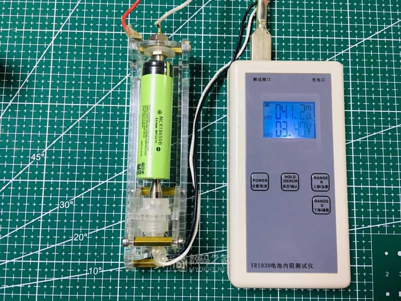
For engineers and procurement teams specifying LiFePO4 battery packs in home energy storage, outdoor power systems, or solar battery house installations, few parameters have as much day-to-day impact as internal resistance. It quietly shapes whether a system holds voltage under load, how hot it runs during peak demand, how quickly it recharges, and how much of its rated capacity is actually usable. Yet internal resistance is easy to overlook—especially when comparing datasheets that emphasize capacity and cycle life but say little about milliohm-level losses inside the cell.
A battery with low internal resistance behaves predictably: terminal voltage stays within a narrow band during discharge, heat buildup remains manageable, and the pack delivers nearly its full energy content even at moderate to high currents. When internal resistance creeps upward, however, the same battery may trigger low-voltage alarms prematurely, waste energy as heat, take longer to charge, and lose usable capacity under real-world loads. This article explains the origins of internal resistance, the conditions that drive it higher, the methods used to measure it, and the design choices that keep it under control in commercial lithium-ion battery pack systems.
Internal resistance is simply the opposition a battery presents to current flow, measured in milliohms. It is not a single resistor hidden inside the cell, but rather the sum of all resistive and electrochemical barriers between the positive terminal, the negative terminal, and the active materials that store energy. These barriers come from electrode materials, electrolyte conductivity, separator properties, current collector foils, weld joints, and even the busbars and BMS components in a finished pack.
When current flows through a LiFePO4 battery pack, the voltage at the terminals drops instantly by an amount proportional to current and resistance—this is Ohm’s Law in action. The drop is always present under load, which is why open-circuit voltage is higher than loaded voltage. The size of that drop depends on how much resistance the current encounters, and it changes constantly with operating conditions.
Two distinct types of resistance contribute to the total. The first is ohmic resistance, which comes from the physical conductive path: the metal foils, tabs, welds, electrolyte, and external connections. This resistance responds instantly when current is applied or removed. In a custom lithium battery pack, poor busbar design, undersized cables, or loose terminal connections can add significant ohmic resistance that was not present in the individual cells.
The second type is polarization resistance, which arises from electrochemical kinetics rather than physical conduction. It includes the energy barrier for charge transfer at the electrode surfaces and the difficulty of moving lithium ions through the electrolyte quickly. Unlike ohmic resistance, polarization resistance builds over time after current starts flowing. That is why a battery’s voltage may drop sharply at the first instant of load, then continue to sag more gradually over the next few seconds or minutes. This two-stage voltage response is a signature of healthy electrochemical behavior and becomes more pronounced as a battery degrades.
Internal resistance is never a fixed number on a datasheet. It moves with temperature, state of charge, age, and chemistry, and a value measured under one set of conditions may mislead if applied to another.
Temperature is the most powerful variable. Cold conditions slow ion movement in the electrolyte and slow the electrochemical reactions at the electrodes, causing resistance to spike. A pack that delivers stable voltage at 25°C can sag badly at 0°C or below. Heat has the opposite short-term effect—resistance drops as ion mobility improves—but sustained high temperatures accelerate aging and cause resistance to grow permanently. For outdoor energy storage systems in hot climates, active thermal management is not optional if long-term resistance stability matters.
State of charge also matters. LiFePO4 cells tend to maintain relatively stable resistance across the middle of their discharge curve—roughly 20% to 80% SoC—but resistance rises near full charge and especially near empty. At very low SoC, the cell’s ability to deliver current weakens, and the terminal voltage collapses quickly under load. System designers who understand this resistance profile can set more accurate low-voltage cutoff points and avoid nuisance shutdowns in home energy storage applications.
Aging and cycle count produce a slow, irreversible increase in internal resistance. Mechanisms include thickening of the solid electrolyte interphase layer on the anode, loss of active lithium, microcracking of electrode particles, and loosening of contact between active material and current collectors. High charge/discharge rates, deep cycling, and extreme temperatures all accelerate this process. Resistance rise typically appears before measurable capacity fade, making it one of the earliest and most reliable indicators of battery health.
Cell chemistry sets the baseline. LiFePO4 cells are known for moderate initial resistance and excellent long-term stability, which suits them well for stationary storage and solar battery house systems. NMC and NCA chemistries may start with lower resistance and suit high-power applications, but they can degrade faster under deep cycling.
The practical consequences of internal resistance show up in four areas that matter to any B2B buyer or integrator.
First, voltage stability. Under load, every milliohm of resistance converts directly into voltage drop. If the drop pushes terminal voltage below the inverter’s minimum input threshold, the system shuts down—even though the battery still holds significant energy. Outdoor energy storage systems that must serve variable loads need low internal resistance to avoid these premature cutoffs.
Second, heat generation. Power lost as heat inside the battery equals current squared times resistance (P = I²R). Because current is squared, heat rises sharply at higher discharge rates, and higher resistance amplifies the problem. A pack with elevated internal resistance runs hotter under the same load, requires more aggressive cooling, and wastes energy that should have gone to the load.
Third, charge acceptance. During constant-current charging, a battery with higher internal resistance reaches its voltage limit sooner. The charger then switches to constant-voltage mode earlier, reducing the charge current and lengthening the time to full charge. For high-power home energy storage systems that need fast recharge during limited solar windows, this is a real operational constraint.
Fourth, usable capacity. Rated capacity is measured under low-current conditions where internal resistance has little effect. Under real load, high resistance causes voltage to hit the cutoff earlier, leaving some energy stranded inside the cell. The gap between rated and usable capacity grows as internal resistance increases and as load current rises.
Two methods dominate industrial testing. The DC pulse method applies a known current step and measures the immediate voltage change to calculate ohmic resistance, then the total voltage drop after a set pulse duration to include polarization effects. It is simple, fast, and directly relevant to real operating conditions, but the numbers depend on pulse length, current, temperature, and SoC. Results are only meaningful when these variables are standardized.
Electrochemical Impedance Spectroscopy (EIS) uses a small alternating current across many frequencies to separate ohmic, charge-transfer, and diffusion resistance components. It provides a much richer diagnostic picture, but requires specialized equipment and trained operators. For most procurement decisions, incoming inspection, and field verification, the DC pulse method is more practical and sufficient.
Minimizing internal resistance starts at the cell level and continues through pack design and system operation.
Cell selection and matching is the foundation. Choose cells with low initial resistance, but also match resistance values between cells in a pack. Unmatched cells create current imbalance, uneven heating, and accelerated degradation—especially in high-capacity LiFePO4 assemblies where small differences become large over time.
Connection design is often an afterthought but can add meaningful resistance. Busbars should be sized for the maximum continuous current with adequate cross-sectional area, terminals should have maximum contact surface, and welds should be consistent. For high-current outdoor storage systems, current density analysis across busbars and connectors can prevent localized hot spots.
Thermal management keeps resistance low in the short term and slows its growth over the battery’s life. Cold-climate solar battery house systems may need battery heating to prevent winter resistance spikes. Hot-climate systems need active cooling to avoid thermally accelerated aging.
Operating discipline also helps. Staying within recommended SoC windows, avoiding unnecessarily high C-rates, and following appropriate charging protocols all reduce the rate of resistance growth. For home energy storage systems where cycle life is the priority, limiting depth of discharge to 80% or less can significantly slow resistance increase and extend usable service life.
Internal resistance is not a minor electrical detail—it is a controlling parameter that determines whether a LiFePO4 battery pack holds voltage, stays cool, charges quickly, and delivers its full rated energy in real conditions. For B2B buyers and system integrators building home energy storage, outdoor energy storage, or solar battery house solutions, understanding internal resistance and managing it through cell selection, pack design, thermal control, and operating parameters is essential to building systems that perform reliably over many years.
Large-format prismatic LiFePO4 cells usually fall between 0.2 mΩ and 1.5 mΩ, while small cylindrical cells can range from 10 mΩ to 50 mΩ. Always compare values under identical test conditions—same SoC, same temperature, same pulse current—because the number shifts with each variable.
The resistance caused by cell chemistry and aging cannot be reversed. However, connection resistance from loose terminals, corroded busbars, or poor welds can be found and corrected. Routine inspection and torque checks on high-current connections help keep pack-level resistance at its designed value.
Resistance increase is one of the earliest warning signs of degradation. As a battery ages, resistance rises while capacity declines. Many BMS platforms track resistance trends alongside capacity to estimate state of health and predict remaining life.
Cold temperatures reduce ion mobility in the electrolyte and slow the electrochemical reactions at electrode surfaces. Both effects increase polarization resistance. In cold-climate outdoor storage systems, preheating may be required before high-current charging or discharging to avoid excessive voltage drop and loss of capacity.
Welcome to contact us:
Inquire more product details from the: Lithium Ion Battery Suppliers
WhatsApp/Wechat/Mobile: +86 13326321310
Email: info@battery-energy-storage-system.com
Website: www.battery-energy-storage-system.com
Ready to power your energy systems with the best in the industry?
Contact us today to get the latest pricing and discuss your needs with our team!
Next:100 pcs CALB 3.7V 113Ah NCM Cells Shipped to New Zealand
Previous:16 pcs A123 3.2V 31Ah LiFePO4 Pouch Cells Shipped to Switzerland