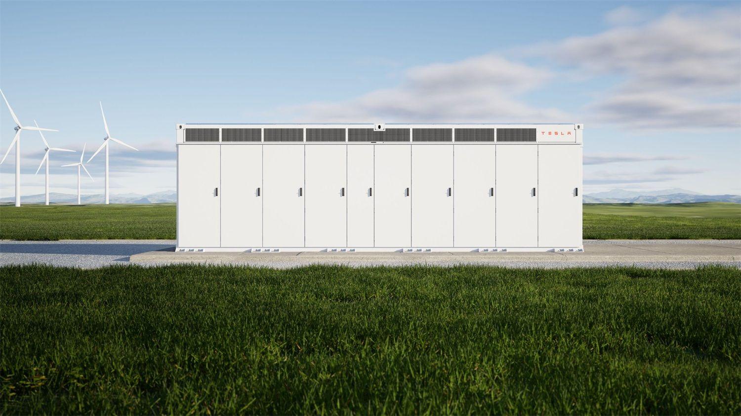
Every modern battery energy storage system depends on a battery management system (BMS) to serve as its supervisory intelligence. The BMS keeps watch over cell voltage, pack current, and temperature. It shields cells from abusive operation. It aligns charge across the pack. It estimates remaining energy and overall battery condition. It also coordinates with inverters, thermal management equipment, and higher-level control software.
For lithium battery energy storage systems expected to remain in service for 10 to 15 years, BMS architecture and system integration are not secondary engineering details. They are choices that directly influence safety, cycle life, and total cost of ownership. A well-designed BMS can identify abnormal behavior within milliseconds and prevent a small irregularity from turning into an expensive failure. A poorly integrated BMS can weaken battery performance, speed up degradation, and even introduce safety hazards.
This guide explains how a battery management system operates in stationary storage. It compares major BMS architectures and their tradeoffs, describes cell balancing methods, and reviews the communication and integration factors that system integrators and procurement teams should assess when specifying or deploying a BESS.
The BMS frequently decides whether a battery reaches its rated design life or fails ahead of schedule. Even high-quality cells can underperform when the BMS manages them poorly—by balancing inaccurately, allowing one cell to drift outside specification, or sending incorrect operating limits to the inverter.
At the same time, a sophisticated lithium battery BMS with precise sensing, dependable algorithms, and reliable protection can extend the service life of even mid-grade cells by preventing abuse and maintaining uniform operating conditions. In commercial and grid-scale storage projects worth millions, BMS selection deserves the same attention as cell chemistry selection.
At its foundation, a battery management system is an electronic control layer that monitors, protects, and optimizes a battery pack or a larger battery system. It occupies the space between the cells and the outside world—the inverter, the thermal management system, and any higher-level energy management software.
In a typical battery energy storage system (BESS), the BMS carries out six main jobs:
- Protection: Guards against overcharge, over-discharge, excessive current, short circuits, and overtemperature events
- Monitoring: Tracks individual cell voltage, pack current, and temperatures across the battery
- Balancing: Keeps cells at comparable charge levels so that weaker cells do not cap the performance of the whole pack
- Estimation: Determines state of charge (SOC) and state of health (SOH) from sensor readings and battery models
- Coordination: Exchanges information with the inverter, thermal management system, and energy management system
- Diagnostics: Identifies faults, logs events, and supplies data for maintenance and warranty review
If measured values cross predefined safety limits, the BMS can reduce current, halt charging or discharging, open contactors to isolate the battery, or issue alarms.
Cell protection is the most fundamental BMS responsibility. The system continuously compares measured values with safe operating boundaries and acts when those boundaries are crossed.
Typical protection triggers and responses include:
| Condition | What Triggers It | How the BMS Responds |
| Overvoltage | Cell voltage rises above the upper limit | Stop charging / disconnect charger |
| Undervoltage | Cell voltage drops below the lower limit | Stop discharge / disconnect load |
| Overcurrent | Charge or discharge current exceeds the limit | Reduce or interrupt current |
| Short circuit | Extreme current spike detected | Disconnect via contactors / fuses |
| Overtemperature | Temperature leaves the safe range | Reduce power / increase cooling / disconnect |
| Undertemperature charging | Cell is too cold to charge safely | Block charging until warmed |
| Ground fault | Insulation resistance falls below threshold | Alarm and isolate the system |
Protection events are normally logged with timestamps, cell identifiers, and measured values. This creates an audit trail that helps with maintenance, troubleshooting, and warranty claims.
The BMS gathers data from sensors placed throughout the battery system:
- Individual cell voltage: Measured at every series-connected cell. Voltage differences can point to imbalance, degradation, or a weak cell.
- Pack current: Captured through shunt resistors or Hall-effect sensors. Current data supports SOC calculations and overcurrent protection.
- Temperature: Sensors are positioned around cells, modules, busbars, and enclosures to detect overheating and guide thermal management.
- Insulation resistance: Monitored in high-voltage systems to catch ground faults before they become serious hazards.
How many sensors are used, and where they are placed, directly affects measurement accuracy and fault detection. Larger systems generally rely on more sensors spread across more monitoring points.
State of charge (SOC) estimates how much usable energy remains in the battery, shown as a percentage. State of health (SOH) reflects the battery’s remaining capacity or condition compared with its original rated value.
SOC and SOH cannot be measured directly. They must be inferred from multiple sensor inputs and battery models. Basic BMS designs use voltage-based estimation or coulomb counting, which integrates current over time. More advanced systems apply model-based estimation and Kalman filtering algorithms that combine real-time sensor data with electrochemical or equivalent-circuit battery models to improve accuracy.
SOH estimation usually accounts for:
- Capacity fade over cycles
- Growth in internal resistance
- Cycle history and throughput
- Calendar aging and temperature exposure
Accurate SOH information helps operators plan maintenance, decide when battery augmentation or replacement is needed, and optimize asset utilization.
Beyond basic protection, modern BMS platforms perform fault detection and diagnostics:
- Cell voltage divergence: Detects when one or more cells drift from the pack average, signaling imbalance or degradation
- Temperature anomaly detection: Identifies cells or modules running hotter than their neighbors
- Internal short detection: Recognizes abnormal voltage or current patterns that may indicate an internal short circuit
- Communication loss detection: Alerts when a monitoring module or sensor stops communicating
- Contact state monitoring: Confirms that contactors and relays operate as expected
These diagnostic functions allow operators to catch developing problems early, before they turn into unplanned outages or safety incidents.
The architecture of a BMS determines how monitoring and protection tasks are distributed across the battery system. Three common approaches are used in energy storage applications.
A centralized BMS relies on one primary controller to monitor and protect all cells in the battery system. Every cell voltage and temperature signal is wired back to a single master board.
Strengths:
- Simpler design and lower hardware cost
- Easier configuration and commissioning
- Fewer communication nodes to manage
Limitations:
- Extensive wiring harness from all cells to the central controller
- Limited scalability—adding modules requires rewiring
- A failure in the central controller can affect the entire system
- Poor fault isolation—pinpointing the exact faulty cell can be difficult
Centralized BMS designs are most common in smaller residential energy storage systems and smaller commercial battery packs.
A distributed BMS places smaller monitoring controllers, often called slaves, directly at each battery module or cell group. These local controllers collect and process cell-level data before communicating with a master controller over a communication bus.
Strengths:
- Reduced wiring—only communication cables run between modules and the master
- Improved measurement accuracy through local signal conditioning
- Better fault isolation—the master can identify which module has the issue
- Easier scalability—additional modules can be added without rewiring the entire system
Limitations:
- Higher hardware cost per module
- More complex communication architecture
- Requires reliable inter-module communication
Distributed architectures are standard in larger commercial and industrial battery energy storage systems and grid-scale BESS.
A modular BMS, also called a master-slave BMS, combines local monitoring controllers with a central master controller. Each module has its own slave board that handles cell voltage monitoring, temperature sensing, and local balancing. The master controller manages overall battery operation, communicates with the inverter, and coordinates system-level protection.
This hybrid approach provides:
- Rapid local response to cell-level protection events
- Scalability for multi-module systems
- Centralized system-level control and communication
- Flexibility to configure the system to specific project requirements
Modular BMS is the dominant architecture in medium-to-large energy storage systems, balancing cost, scalability, and performance.
Battery cells do not age at exactly the same rate. Manufacturing tolerances, temperature variations, and different charge histories cause individual cells to develop slightly different capacities and self-discharge rates. Over time, these differences cause cells within a series string to drift to different states of charge.
The weakest cell in a series string limits the entire pack. If one cell reaches the undervoltage cutoff first during discharge, the whole pack must stop—even if other cells still have capacity. Similarly, if one cell reaches the overvoltage limit first during charging, charging must stop before other cells are fully charged.
Cell balancing reduces this effect by equalizing charge levels across cells.
Passive cell balancing removes excess energy from higher-voltage cells by dissipating it through resistors as heat. The BMS activates a balancing resistor across a cell when its voltage exceeds the pack average, bleeding off energy until all cells are at a similar level.
Strengths:
- Simple, inexpensive hardware
- Proven technology with wide adoption
- Easy to implement and maintain
Limitations:
- Wastes energy as heat
- Generates heat that must be managed
- Limited balancing current, typically 50–200 mA per cell
- Slower balancing—may require multiple charge cycles
Passive balancing is common in residential battery systems and smaller commercial packs where balancing losses and heat generation are acceptable.
Active cell balancing transfers energy from higher-charged cells to lower-charged cells using DC-DC converters or capacitor-based charge shuttles. Instead of wasting excess energy as heat, it moves it to cells that need it.
Strengths:
- Higher energy efficiency—minimal energy wasted as heat
- Faster balancing with higher balancing currents
- Better temperature management
- Improved pack utilization and available capacity
Limitations:
- More complex and expensive hardware
- Additional components that can fail
- More complex control algorithms
Active balancing is generally found in larger commercial energy storage systems and high-value applications where the energy savings and performance improvements justify the extra cost.
The BMS must communicate with the inverter, also called the PCS, the thermal management system, and often an energy management system. Common communication protocols include:
- CAN bus: The dominant protocol in automotive and many BESS applications. Robust, real-time, and widely supported.
- Modbus RTU over RS-485: Common in industrial and smaller commercial systems. Simple and widely compatible.
- Modbus TCP / Ethernet: Used in larger systems with network-based control.
- CANopen: Used in some industrial and marine applications.
- RS-232: Legacy interface, mostly used for commissioning and diagnostics.
Typical data exchanged between BMS and inverter includes:
- SOC and SOH estimates
- Maximum charge and discharge current limits
- Battery voltage and temperature status
- Protection warnings and fault codes
- System alarm status
Protocol compatibility must be verified before purchasing or commissioning a BESS. If the BMS cannot communicate directly with the selected inverter, a protocol converter may be required, adding complexity and another potential failure point.
In a complete energy storage system, three controllers operate at different levels:
- BMS (Battery Management System): Operates at the cell level. Protects cells, manages balancing, estimates SOC and SOH, and ensures safe battery operation.
- PCS (Power Conversion System): Operates at the electrical level. Converts battery DC power to AC, or vice versa, and controls power flow between the battery and the grid or loads.
- EMS (Energy Management System): Operates at the system level. Determines when and how much to charge or discharge based on electricity prices, load demand, solar generation, and grid signals.
In small residential systems, some EMS functions may be integrated into the inverter. In larger commercial and grid-scale installations, a dedicated EMS coordinates multiple battery units, solar inverters, and other loads. The BMS reports battery status and limits to the PCS, while the EMS sends setpoints and dispatch signals to the PCS.
A BMS provides continuous monitoring and automatic protection. When it detects abnormal voltage, current, or temperature conditions, it can limit battery operation or disconnect the battery from the system through contactors.
Temperature monitoring is especially critical. If battery temperature approaches a defined limit, the BMS can:
- Reduce charging or discharging power
- Signal the thermal management system to increase cooling
- If conditions continue to deteriorate, initiate a controlled battery shutdown
The key safety advantage is early detection. Problems can be identified at the cell or module level—often before they are visible to operators or system-level controls—preventing minor issues from developing into larger failures.
For larger installations, BMS protection events are logged with timestamps and measured values. These logs support root-cause analysis, warranty claims, and continuous improvement of maintenance procedures.
A dependable battery management system is fundamental to modern battery energy storage. It does far more than monitor voltage—it integrates cell protection, balancing, temperature monitoring, SOC and SOH estimation, fault detection, and communication with the PCS and EMS.
For residential energy storage, commercial battery systems, and grid-scale BESS projects, choosing the right BMS architecture, verifying communication compatibility, and ensuring robust protection and diagnostics are critical design decisions. The BMS sits at the intersection of cell-level safety and system-level control, and its quality directly determines whether a battery system delivers its rated performance, safety, and service life.
When properly integrated with the PCS, EMS, and thermal management system, the BMS helps the battery operate safely, efficiently, and reliably throughout its 10 to 15 year design life. For system integrators and procurement teams, evaluating BMS specifications alongside cell chemistry and pack design is essential for deploying storage systems that perform as expected, remain safe, and deliver long-term value.
A BMS is the electronic control unit responsible for monitoring, protecting, and optimizing a battery pack. It reads cell voltage, current, and temperature; prevents overcharge, over-discharge, and overcurrent; manages cell balancing; estimates SOC and SOH; and communicates with the inverter and thermal management system. Without a well-designed BMS, safe, reliable, and long-lived battery operation is difficult to achieve in any storage application.
Passive balancing burns off excess energy from higher-voltage cells through resistors, releasing it as heat. It is simple and low-cost, but it wastes energy and creates heat. Active balancing moves energy from higher-charged cells to lower-charged cells using DC-DC converters, making it more efficient and faster, though it requires more expensive hardware. Residential systems commonly use passive balancing, while larger commercial and industrial storage often adopts active balancing when efficiency gains justify the cost.
SOC cannot be measured directly. The BMS estimates it by combining sensor inputs—voltage, current over time through coulomb counting, and temperature—with battery models. Basic systems rely on voltage-based estimation or coulomb counting alone. More advanced platforms use model-based estimation and Kalman filtering to continuously refine SOC by comparing predicted battery behavior with real-time measurements, improving accuracy under changing load and temperature conditions.
Common options include CAN bus, Modbus RTU over RS-485, Modbus TCP, and CANopen. The BMS sends SOC, SOH, current limits, temperature status, and fault codes to the inverter. Compatibility between the BMS and inverter must be confirmed before purchase and commissioning. If the two cannot communicate directly, a protocol converter may be required, adding cost and complexity.
The decision among centralized, distributed, and modular BMS designs depends on system size, scalability needs, and budget. Centralized BMS is suitable for small residential systems where simplicity and cost are primary concerns. Distributed or modular BMS is preferable for commercial and grid-scale systems where fault isolation, scalability, and measurement accuracy are critical. When comparing BMS options, examine sensor count and placement, balancing method, communication protocols, protection features, diagnostic capabilities, and the supplier’s track record with similar installations.
Welcome to contact us:
Inquire more product details from the: Lithium Ion Battery Suppliers
WhatsApp/Wechat/Mobile: +86 13326321310
Email: info@battery-energy-storage-system.com
Website: www.battery-energy-storage-system.com
Ready to power your energy systems with the best in the industry?
Contact us today to get the latest pricing and discuss your needs with our team!
Next:None
Previous:50 pcs of Sunwoda 3.7V 173Ah NMC Lithium Battery Cells Shipped to the USA